Ultrasonic Homogenizer FAQ: Probe Size, Power & Troubleshooting
Choosing the right ultrasonic homogenizer configuration is critical for achieving consistent cavitation, efficient energy transfer, and reproducible laboratory results. This FAQ guide covers probe size selection based on sample volume, differences between ultrasonic power and intensity, temperature control during sonication, and common troubleshooting issues such as foaming or overheating.
Whether you are using a handheld probe sonicator for small-volume cell disruption or an industrial ultrasonic homogenizer for nanoparticle dispersion, understanding these parameters will significantly improve performance and reliability.
Selecting the proper probe size is critical for efficient sonication. As a general guideline, a ½” probe processes approximately 20–250 ml, microtips are recommended for volumes below 50 ml, and a 1” probe is suitable for 1 liter processing. Vessel geometry also matters — even if 20 ml falls within the ½” range, the probe may not physically fit inside a narrow tube, in which case a microtip is a better option. Small tips generate higher intensity and heat more quickly, so pulse mode is recommended to prevent overheating. For larger volumes, bigger probes improve processing efficiency and reduce time; for volumes above 1 liter, using a stir bar can further increase effectiveness. There is no absolute volume limit for any probe, as final selection depends on material properties and vessel shape.
| Probe Tip Diameter |
Process Volume Range |
Amplitude Microns |
Probe Length |
Materials final size |
|---|---|---|---|---|
| 1/16″ (1.6 mm) | 0.2 ml ~ 15 ml | 320 μm | 9 cm | 2 ~3 nanometer |
| 1/8″ (3.2 mm) | 0.5 ml ~ 25 ml | 180 μm | 14 cm | 3 nanometer |
| 1/4″ (6.4 mm) | 10 ml ~ 100 ml | 120 μm | 11 cm | 3 nanometer |
| 8.0 mm | 10 ml ~ 200 ml | 100 μm | 11 cm | 3 nanometer |
| 9.0 mm | 10 ml ~ 250 ml | 90 μm | 10 cm | 4 nanometer |
| 10.0 mm | 20 ml ~ 300 ml | 80 μm | 10 cm | 4 nanometer |
| 1/2″ (12.7mm) | 20 ml ~ 300 ml | 60 ~ 120 μm | 13 cm | 3 ~5 nanometer |
| 16.0 mm | 20 ml ~ 600 ml | 70 | 13 cm | 5 nanometer |
| 3/4″ (19.1mm) | 50 ml ~ 800 ml | 60 μm | 28 cm | 5 nanometer |
| 20.0 mm | 50 ml ~ 900 ml | 55 ~80 μm | 28 cm | 7 nanometer |
| 1″ (25.4mm) | 100 ml ~ 1000 ml | 35 μm | 28 cm | 7 nanometer |
| 30.0 mm | 100 ml ~ 3 litre | 35 μm | 30 cm | 8 nanometer |
| 40.0 mm | 1000 ml ~ 25 litre | 25 μm | 30 cm | 10 nanometer |
| 50.0 mm | 1000 ml ~ 30 litre | 30 μm | 50 cm | 10 nanometer |
* Depends on the frequency & probe design, the vibration amplitude will also change accordingly. however, the principle & philosophy is same.
* The processed material’s final size depends on the processing duration time, and material’s characteristics & propertites.
* The probe length & total length will be different according to frequency & design.
* The probe length & tip diameter are all customizable.
Power is the electrical energy delivered to the converter and displayed in watts, while intensity is directly related to amplitude — the actual mechanical vibration of the probe tip. Amplitude determines how aggressively the sample is processed, and it is the most critical parameter for reproducible results. For example, a ½” probe at 100% may reach approximately 120 μm amplitude, and at 50% around 60 μm. Power consumption, however, varies depending on sample viscosity and load — a viscous sample requires more watts even at the same amplitude. Therefore, consistent sonication results depend primarily on maintaining stable amplitude, temperature, and sample conditions rather than focusing solely on wattage readings.
Temperature rise during sonication is caused by energy dissipation from cavitation and mechanical vibration. Excessive heat can denature proteins, degrade sensitive materials, or alter reaction conditions, so temperature control is critical for reproducible results. Effective cooling methods include using pulse mode to reduce continuous energy input, combining pulse mode with an ice bath, using CoolRack systems to stabilize and chill samples, or employing external chillers for higher power applications. Standard probes are approved for liquid temperatures up to 140°F (60°C), but maintaining lower temperatures is recommended for heat-sensitive samples.
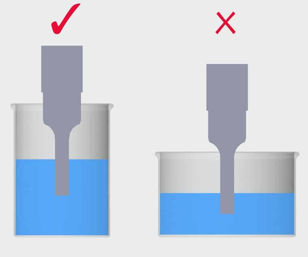
Probes must be submerged at the correct depth to ensure proper cavitation and sample circulation. If the tip is positioned too close to the surface, air will be drawn into the liquid, causing foaming and poor processing efficiency. If the tip is inserted too deeply, circulation becomes restricted and energy distribution is reduced. Both situations can negatively affect results. Foaming is more common in small volumes (below 1 mL) and when amplitude settings are excessively high.
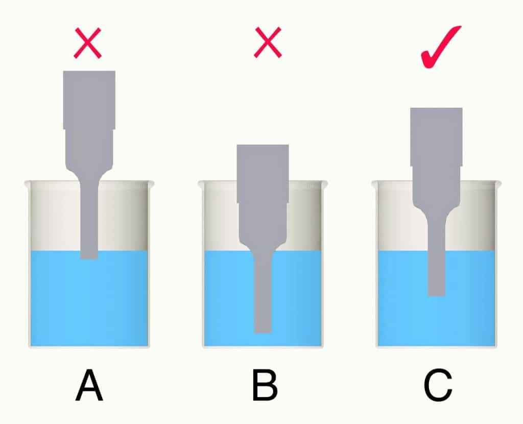
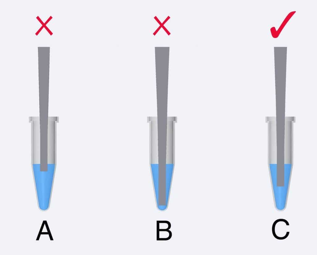
As illustrated above, Figure A introduces air and causes foam formation, resulting in inefficient processing. Figure B limits fluid circulation and reduces cavitation efficiency. Figure C represents the optimal setup, allowing effective energy transfer and faster processing time.
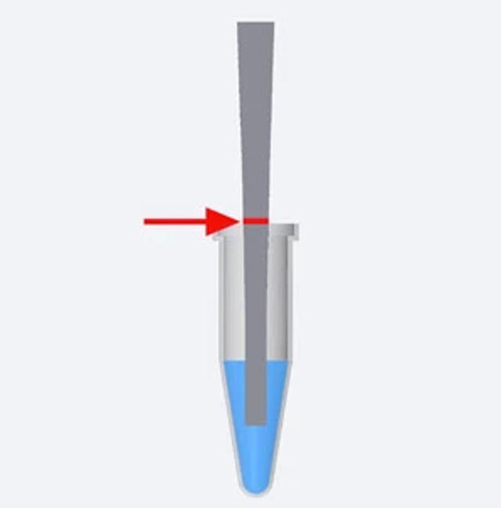
When tubes are placed in ice baths for temperature control, the liquid level can be difficult to observe. To maintain consistent positioning, we recommend marking the correct insertion depth on the probe with a permanent marker. This ensures reproducible tip placement, even when the tube is submerged in ice.
The watts displayed on the generator screen represent the electrical power delivered to the converter. However, not all of this power is transferred into the sample. The actual energy delivered depends on load conditions and probe resistance.
To estimate the power delivered to the sample:
-
Turn on the equipment.
-
Set the desired amplitude.
-
With the probe in air (no sample), record the wattage displayed.
-
Without changing amplitude, immerse the probe into the sample and record the new wattage.
-
The difference between these two readings represents the approximate power delivered to the sample (in watts).
To calculate ultrasonic intensity (power density, W/cm²):
Intensity = Power delivered (W) ÷ Probe tip area (cm²)
Probe tip area is calculated as:
Area = π × r²
or
Area = π × (diameter / 2)²
Example using a 3 mm probe:
Diameter = 3 mm = 0.3 cm
Radius = 0.15 cm
Area = π × (0.15)² = 3.142 × 0.0225 = 0.0707 cm²
If 1 watt is delivered to the sample:
Intensity = 1 ÷ 0.0707 = 14.14 W/cm²
Note: This method provides an approximate estimation of ultrasonic intensity and does not account for acoustic losses in the liquid.
Ultrasonic homogenization requires optimization of amplitude, pulse mode, and processing time to achieve reproducible results.
-
Start by testing your probe in water using the same volume and vessel geometry as your actual application. Observe cavitation behavior and liquid circulation at different amplitude settings. Proper cavitation should produce uniform mixing without excessive foaming or splashing.
-
Select an amplitude that provides effective cavitation without overheating or sample degradation. Smaller volumes typically require lower amplitude and shorter pulse cycles to control temperature rise. Larger volumes may require higher amplitude to maintain sufficient energy density.
-
Perform a time study. Process identical samples at different time intervals and evaluate particle size, dispersion quality, or cell disruption efficiency. Adjust amplitude and duration based on measurable results rather than visual observation alone.
-
For advanced applications (e.g., nanoparticle dispersion, emulsification, cell lysis), optimization should consider energy density (W/cm²), total energy input (J), and temperature profile to ensure reproducibility.
Validated parameter ranges for common applications are available upon request.
Nanoparticle dispersion typically requires high energy density and sufficient processing time to break particle agglomerates effectively. Probe selection should be based on sample volume and required intensity rather than size alone.
For small-volume nanoparticle suspensions (e.g., 5–50 mL), smaller diameter probes (3–8 mm) often provide higher localized energy density, which improves deagglomeration efficiency. However, they may generate faster temperature rise and tip erosion during extended processing.
For medium to larger volumes (≥50 mL), larger diameter probes (12–20 mm) allow more uniform energy distribution and improved processing efficiency. Larger probes are also mechanically more robust and typically exhibit slower wear during long-duration dispersion processes.
In practice, optimal probe size should balance:
-
Energy density (W/cm²)
-
Total energy input (J)
-
Sample volume
-
Temperature control
-
Desired final particle size
Application-specific parameter optimization is recommended to achieve reproducible nanoparticle dispersion results.
Vessel geometry significantly influences ultrasonic homogenization efficiency. Ultrasonic energy is generated at the probe tip and propagates downward, creating axial flow and radial circulation patterns within the liquid.
Tall, narrow vessels generally promote more efficient energy distribution because the downward flow and upward recirculation are confined, allowing better mixing of the entire sample volume. In wide vessels, the circulation path becomes longer and energy density decreases toward the periphery, which may result in incomplete processing at the edges.
For optimal performance:
-
Use a vessel diameter slightly larger than the probe diameter
-
Maintain sufficient liquid height above the probe tip
-
Avoid excessively wide containers for small volumes
-
Ensure the probe does not touch the sides or bottom of the vessel
Proper vessel selection improves mixing efficiency, reduces processing time, and enhances result reproducibility.
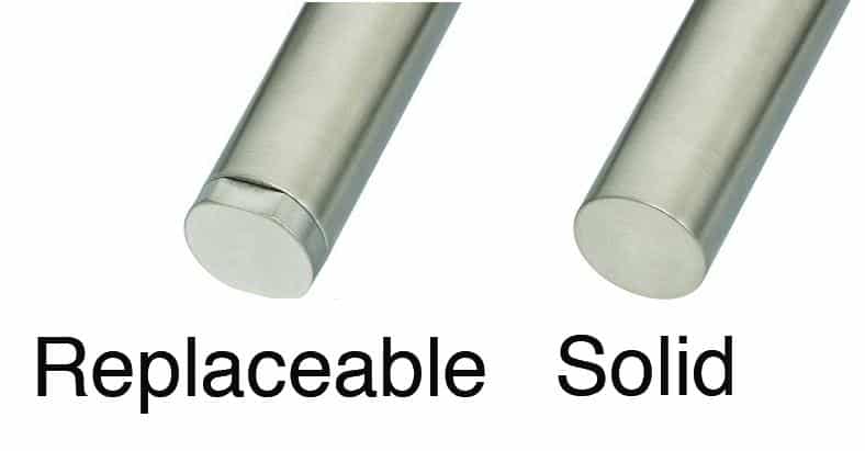
Replaceable tip probes are typically used for aqueous samples. These probes have a threaded, removable tip that can be replaced once worn, reducing maintenance cost.
However, when processing samples containing organic solvents, alcohols, or other low surface tension liquids, fluid can penetrate the threaded interface—regardless of how tightly it is assembled. Once liquid enters the internal joint, it may loosen the connection, affect acoustic transmission, and potentially overload the generator.
For solvent-based or low surface tension applications, a solid one-piece probe is strongly recommended. Solid probes have no threaded interface, providing improved structural integrity, better acoustic coupling, and higher operational reliability. Solid probes can be used for both aqueous and solvent systems.
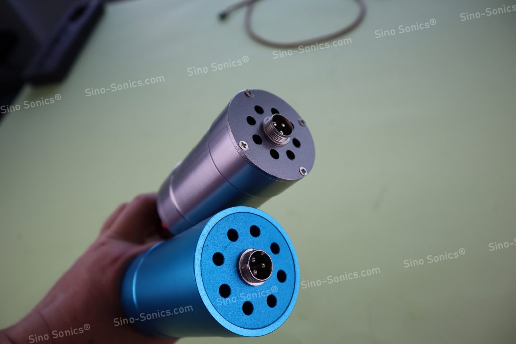
During long sonication cycles, heat generated at the probe tip travels upward through the horn to the converter. If excessive heat builds up, it can damage the piezoelectric elements and reduce the lifespan of the ultrasonic homogenizer system.
For continuous or heavy-duty applications, proper cooling is essential. Industrial ultrasonic converters are typically designed with integrated cooling fans or forced-air ventilation to maintain stable operating temperatures and ensure reliable 24/7 operation.
Insufficient cooling may lead to reduced performance, automatic overload protection, or permanent damage to the converter.
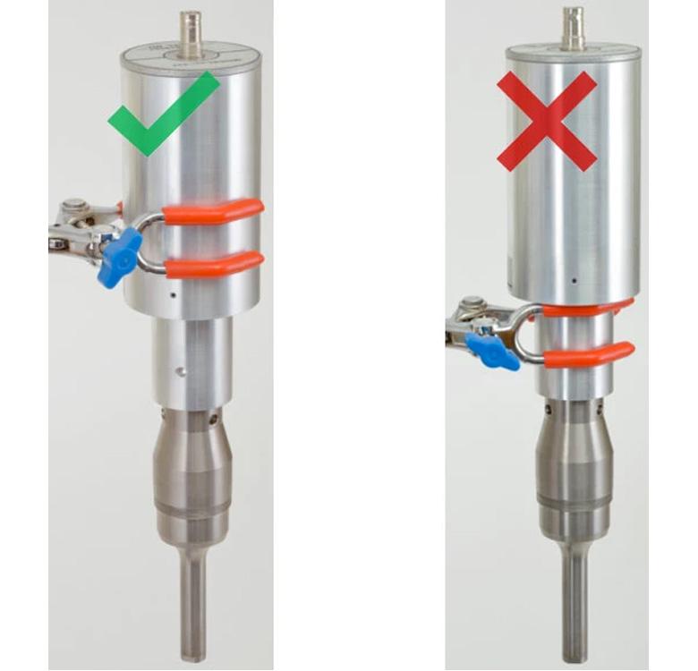
Improper clamping can damage the converter, reduce performance, and void the warranty. The clamp must never be attached to the active vibrating section of the converter or horn, as this area experiences longitudinal oscillation during operation.
Clamping on a vibrating section restricts movement, alters resonance characteristics, increases mechanical stress, and may cause overheating or internal piezoelectric failure.
The converter should only be clamped at the designated mounting area (non-vibrating section), typically near the nodal point specified by the manufacturer.
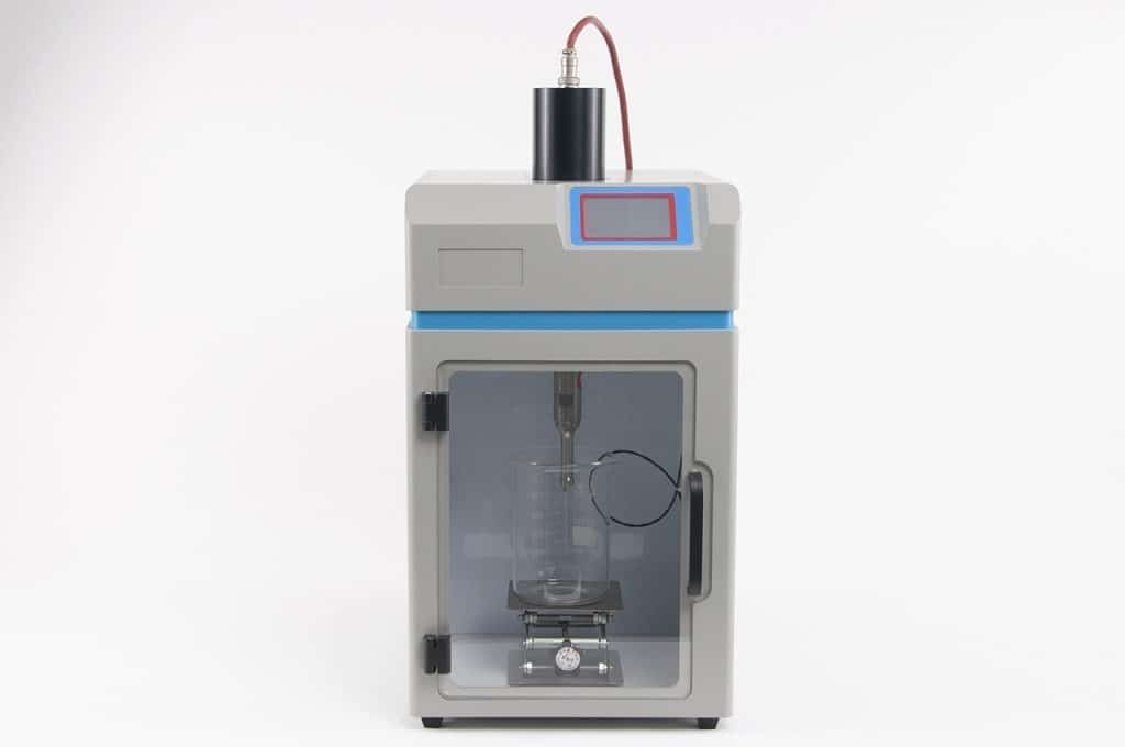
Using a properly designed stand or enclosure ensures correct positioning and stable operation.
A booster horn is used to increase or decrease the amplitude delivered from the ultrasonic converter to the probe. It changes the vibration ratio between the converter and the horn, allowing higher intensity output without increasing generator power.
For example, a 2:1 booster can double the amplitude of a 1” probe, significantly reducing processing time when working with larger volumes. A 1 liter sample can often be processed much faster when a properly matched booster is used.
Small diameter probes already operate at high intensity and should not be used with high-gain boosters, as excessive amplitude may cause probe fatigue or cracking.
Boosters are typically recommended for high-volume processing, viscous materials, or applications requiring higher energy density.
Ultrasonic homogenization generates high-frequency noise, typically exceeding 85 dB during operation. Prolonged exposure to this noise may cause discomfort and is not recommended without proper protection.
A sound enclosure can significantly reduce operating noise (typically by up to 20 dB, depending on configuration and environment), creating a safer and more comfortable working environment.
Our sound enclosure is designed to securely support the converter and probe assembly, eliminating the need for an additional stand or clamp while improving operational stability.
Multiple enclosure models are available to accommodate different system configurations and accessories.