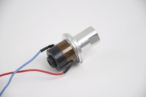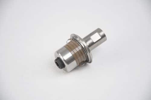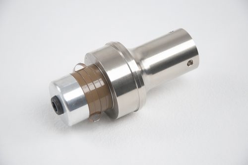
An ultrasonic system that runs poorly is often not broken — it is simply out of tune. A transducer stack that is slightly off resonance, a booster that no longer matches its sonotrode, or a batch of ceramic rings that arrived 200 Hz off-spec will all cause the generator to compensate, overload, or hunt. None of these faults are visible to the eye, and none of them show up in a multimeter measurement. They show up in an impedance sweep.
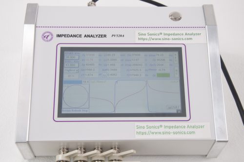
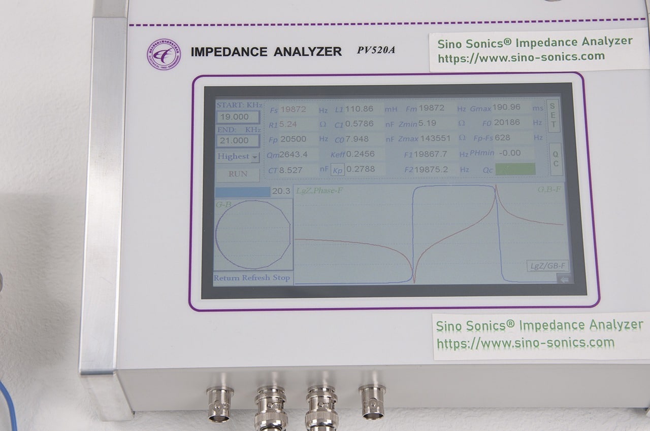
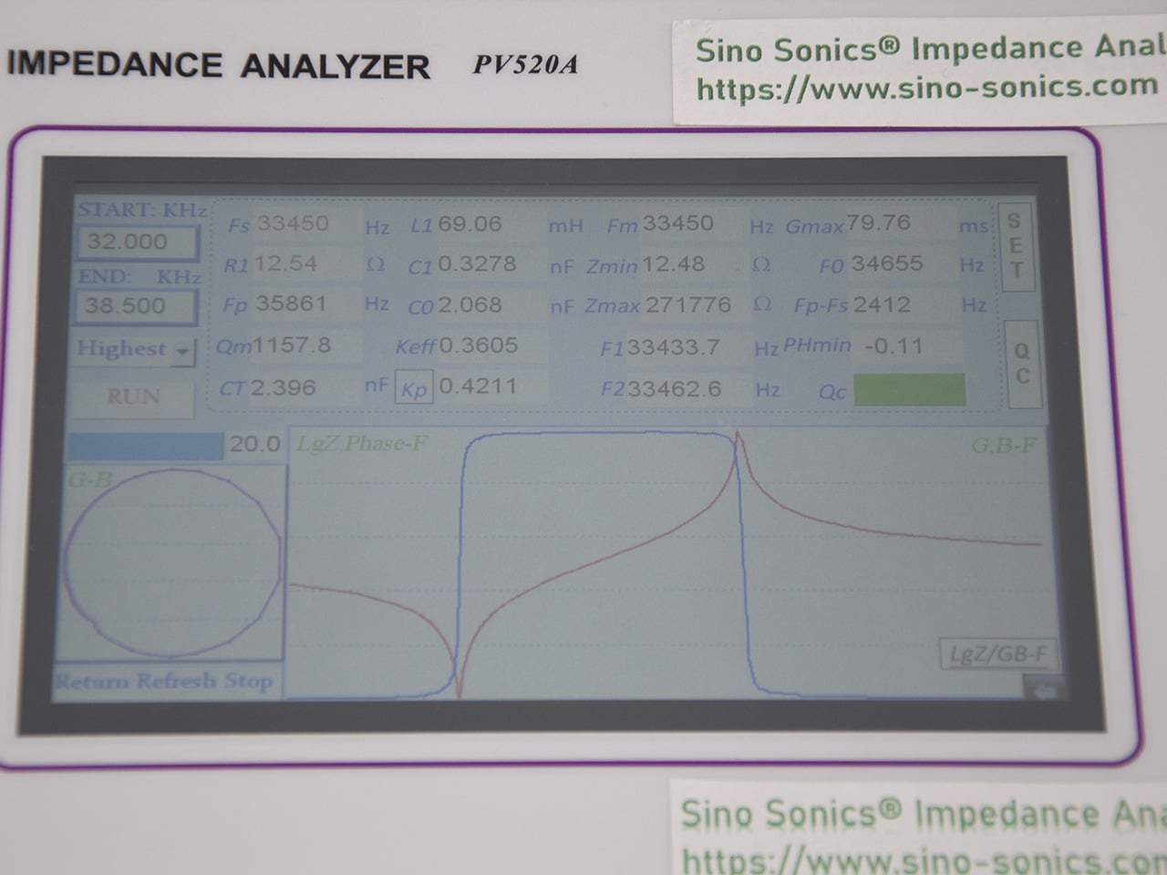
The ultrasonic impedance analyzer is the instrument that makes these invisible problems visible. It sweeps a frequency range, measures the complex electrical impedance at each point, and plots the result as a curve — from which resonant frequency, anti-resonant frequency, mechanical quality factor (Qm), and a dozen other parameters can be read directly.
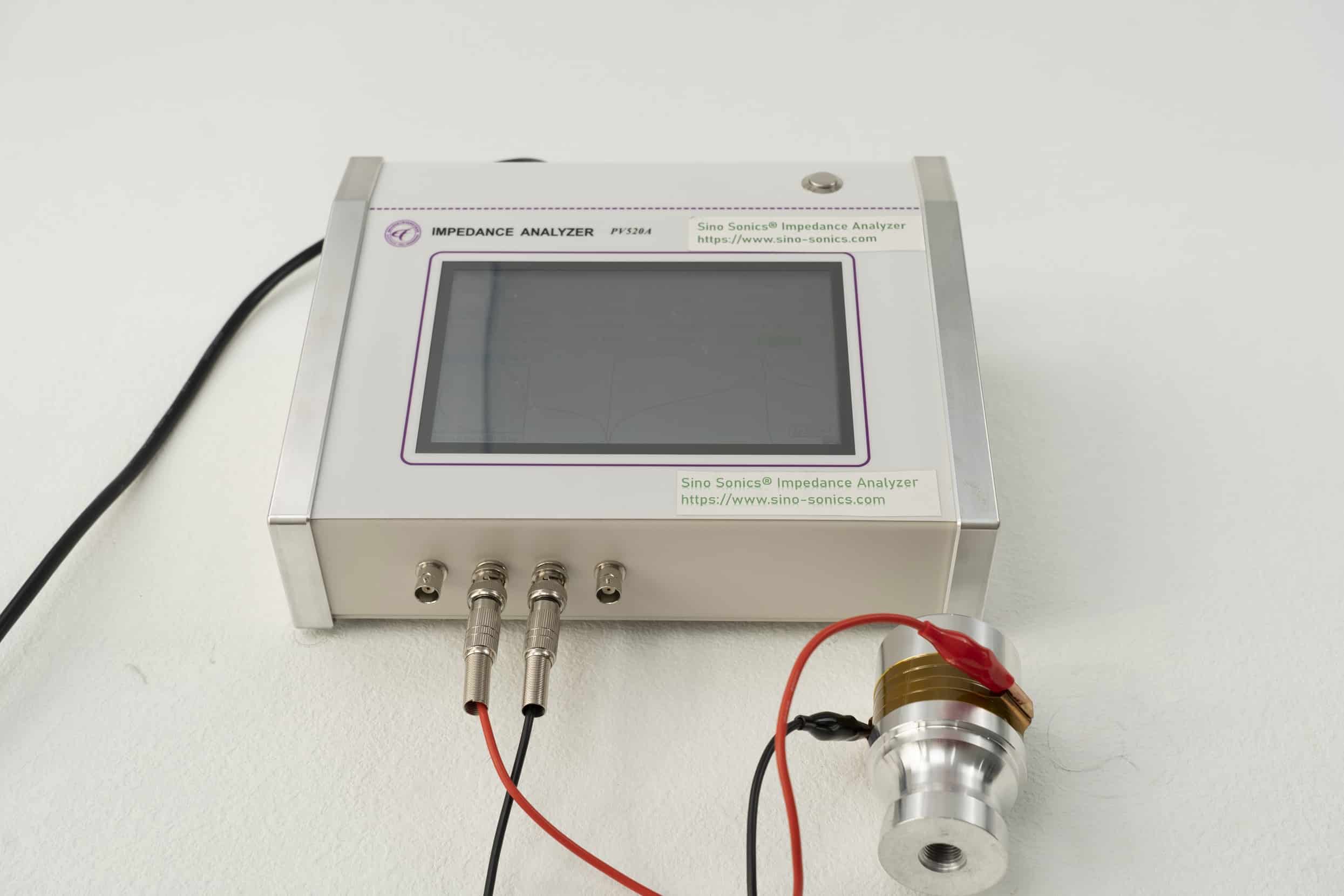
This guide explains what an impedance analyzer measures, how to use it for transducer QC and troubleshooting, and what the Sino Sonics PV520A offers across each application.
Key takeaways
- PV520A measures 21 parameters including Fs, Fp, Qm, and motional R1/L1/C1.
- Three models span 1 kHz–1/3/5 MHz, ±0.04% to ±0.02% accuracy, from $2,300.
- Sweeps 1,000 points in 5 seconds via a 7.8-inch touchscreen.
- Comparable accuracy to the Agilent 4294A at about one-tenth the $25,000 cost.
- Includes a 1-year warranty; QC accepts Fs within ±50 Hz and Qm ≥1,800 for PZT-8.
Why Impedance Measurement Matters in Ultrasonics
Every ultrasonic transducer has a natural resonant frequency — the frequency at which the piezoelectric stack and its attached mechanical mass vibrate with maximum amplitude for a given input power. At resonance, the electrical impedance of the transducer drops to a minimum (at the series resonance frequency Fs) and then rises to a maximum (at the parallel resonance frequency Fp). The distance between these two peaks, and the sharpness of the resonance curve, encode the transducer’s entire mechanical health.
If you cannot measure this curve, you are operating blind. Common situations where impedance measurement resolves the question quickly:
- Incoming quality control — a batch of new ceramic rings or assembled transducers needs to pass a frequency and Q test before acceptance
- Fault isolation — the welding machine’s generator is throwing overload faults; is the fault in the generator, the transducer, the booster, or the sonotrode?
- Stack matching — a technician is building a new transducer; the booster and sonotrode must be tuned to within a few Hz of the transducer to maximize energy transfer
- Aging check — a transducer that has been in service for one years needs a baseline comparison to the original measurement to determine whether ceramic aging has shifted the frequency outside the generator’s tracking range
What the PV520A Measures
The Sino Sonics PV520A impedance analyzer sweeps from 1 kHz to 1 MHz (S model), 3 MHz (T model), or 5 MHz (V model) and measures 21 parameters on every sweep:
| Parameter Group | Parameters |
|---|---|
| Resonance frequencies | Fs (series resonance), Fp (parallel anti-resonance) |
| Admittance / impedance | Gmax (maximum conductance), F1/F2 (half-power frequencies) |
| Mechanical quality | Qm (mechanical quality factor) |
| Capacitance | CT (free capacitance), C0 (clamped capacitance) |
| Dynamic equivalent circuit | R1, L1, C1 (motional branch values) |
| Coupling coefficients | Keff (effective electromechanical coupling), Kp (planar coupling) |
| Dielectric properties | Free dielectric constant |
For most transducer QC and tuning work, the critical outputs are Fs, Fp, Qm, and the impedance curve shape. The equivalent circuit values (R1, L1, C1) are needed for generator design and drive circuit matching.
PV520A Model Comparison
| Model | Frequency Range | Basic Accuracy | Starting Price |
|---|---|---|---|
| PV520A-S | 1 kHz – 1 MHz | ±0.04% | From $2,300 / set |
| PV520A-T | 1 kHz – 3 MHz | ±0.04% | Contact for pricing |
| PV520A-V | 1 kHz – 5 MHz | ±0.02% | From $3,650 / set |
For ultrasonic welding and homogenizer transducers (15–40 kHz range), the PV520A-S covers all standard frequencies with room to spare. The PV520A-T and PV520A-V are used when the application includes high-frequency cleaning transducers (up to 170–235 kHz), HIFU medical transducers, or sensor characterization up to the MHz range.
All three models share the same 7.8-inch touchscreen interface, the same 5-second / 1,000-point sweep speed, and the same PC software. Frequency accuracy is ±10 ppm; phase accuracy is 0.15°; impedance range is 1 Ω to 1 MΩ.
The PV520A was co-developed with Tsinghua University’s Department of Automation and the Institute of Acoustics, Chinese Academy of Sciences. It has been cited in peer-reviewed publications including *Sensors* (MDPI, 2017) and *Coatings* (MDPI, 2023). Its measurement performance benchmarks against the Agilent 4294A at less than one-tenth the cost.
Application 1: Incoming QC on Piezoelectric Ceramic Rings
Tip: For incoming QC on PZT-8 rings, accept Fs within ±50 Hz of nominal and require Qm of at least 1,800.
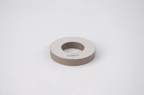
When a batch of piezoceramic rings arrives from a supplier, the stated specs on the data sheet may not reflect the actual batch. Firing variations in sintering, composition drift, and handling damage all cause rings to arrive off-spec. Without a measurement, these rings enter the transducer stack and cause tuning problems that only appear after assembly — wasting assembly labor and potentially damaging the generator.
QC procedure:
- Place the ring in the test fixture (the PV520A ships with standard fixtures for ring and disk elements)
- Set the sweep range to cover ±20% around the expected resonant frequency
- Run a 5-second sweep
- Read Fs, Fp, and Qm from the instrument display or PC software
- Accept or reject against the specification: Fs within ±50 Hz of nominal, Qm above the material floor (e.g., ≥ 1,800 for PZT-8 rings)
For matched-stack transducers — where 4–8 rings must resonate within ±10 Hz of each other — measure each ring individually and sort by frequency before stack assembly. This step, impossible without an impedance analyzer, is the difference between a transducer that reaches its rated power smoothly and one that hunts or runs hot.
Application 2: Diagnosing Transducer Faults
A failing transducer is often confused with a failing generator. The generator throws overload errors, amplitude fluctuates, and weld quality deteriorates — but these symptoms fit both failure modes. Before ordering a new generator, measure the transducer.
Measurement procedure for a suspected faulty transducer:
- Disconnect the transducer from the generator and booster — measure it as a standalone unit
- Connect test leads to the transducer’s electrical terminals
- Sweep the expected operating frequency range (e.g., 18–22 kHz for a 20 kHz transducer)
- Compare the resulting curve to the baseline measurement (taken when the unit was new, or to the specification curve)
What the curve tells you:
| Impedance Curve Appearance | Likely Cause |
|---|---|
| Clean, sharp resonance peak at nominal frequency, Qm in spec | Transducer is healthy — look at generator or sonotrode |
| Resonance peak shifted by > 200 Hz | Ceramic aging, temperature-driven frequency drift, or bolt loosening |
| Broadened, low, or absent resonance peak | Ceramic crack, depoling, or stack delamination |
| Two peaks close together (split resonance) | Partial crack in one ring; asymmetric stack contact |
| Very high minimum impedance (Rmin >> spec) | Broken internal connection, cracked electrode, or loose center bolt |
A split resonance — two peaks where there should be one — is almost diagnostic of a cracked ceramic ring. A healthy transducer shows a single clean resonance. Replacing the stack at this point, guided by the impedance measurement, is far less expensive than allowing the fault to cascade into generator damage.
Application 3: Tuning a New Transducer Stack
Building a Langevin-type transducer from ceramic rings, metal masses, and a center bolt requires tuning — matching the assembled stack’s resonant frequency to the target operating frequency of the generator and the booster/sonotrode combination.
Process:
- Assemble the stack loosely (do not torque the center bolt fully)
- Measure impedance — note Fs
- Adjust by adding or removing a thin washer, changing ring thickness, or modifying the front/back mass to shift Fs toward target
- Re-measure until Fs is within ±50 Hz of target
- Torque the center bolt to specification and re-measure — bolt torque shifts resonant frequency (typically upward by 50–150 Hz for a standard stack); account for this offset during assembly
After the transducer is assembled, measure it again with the booster and sonotrode attached in the same configuration as production (clamped, with the sonotrode in free air). The complete assembly resonant frequency is the value the generator must track in operation. If this assembled frequency falls outside the generator’s tracking window, the generator will fault out.
Application 4: Matching Stacks for Multi-Transducer Systems
Note: Match stacks to within ±10 Hz, and keep multi-transducer sets within ±30 Hz for balanced operation.
Some applications require multiple transducers operating in phase — cleaning tanks with multiple bonded transducers on the same wall, multi-probe homogenizers, or vibrating-screen systems with multiple drive points. If the transducers are not matched in frequency, they fight each other rather than cooperating, causing destructive interference and hot spots.
Matching procedure:
- Measure all candidate transducers individually on the PV520A
- Sort by Fs
- Group transducers within ±30 Hz of each other into matched sets
- Install only matched sets in multi-transducer configurations
For cleaning tanks, this matching step is the single most effective way to prevent early transducer failure and uneven cleaning performance.
Application 5: Monitoring Transducer Aging in Service
Piezoelectric ceramics age over time — domain wall motion progressively reduces, causing the resonant frequency to shift upward and Qm to decrease. This is a normal process that is gradual and manageable, not a sudden failure. Scheduled impedance measurements at installation, 6 months, and 12 months establish a trend that identifies when the frequency drift is approaching the generator’s tracking limit.
Recommended monitoring schedule for high-duty welding transducers:
- At installation: record Fs, Fp, Qm, and Rmin as baseline
- At 6 months: re-measure; flag if Fs has shifted by > 100 Hz or Qm has dropped by > 20%
- At 12 months or on first amplitude instability: full diagnostic sweep
This approach avoids unexpected production line stops by scheduling transducer replacement during planned maintenance windows rather than at a production-disrupting failure event.
PV520A vs. Agilent 4294A: The Practical Comparison
The Agilent (now Keysight) 4294A is the traditional reference instrument for piezoelectric impedance measurement. It delivers high accuracy across a wide frequency range but costs upward of $30,000 new, with lead times measured in months.
The PV520A was designed with the same measurement physics but optimized for the transducer factory and quality lab — not the metrology department. Key comparisons:
| Feature | PV520A | Agilent 4294A |
|---|---|---|
| Frequency range (V model) | 1 kHz – 5 MHz | 40 Hz – 110 MHz |
| Accuracy | ±0.02% | ±0.08% basic |
| Sweep speed (1,000 points) | 5 seconds | Longer at equivalent resolution |
| Interface | 7.8″ touchscreen, immediate use | Requires configuration |
| PC software | Included | Separate |
| Training required | None | Moderate |
| Price | From $2,300 | >$25,000 (new) |
For transducer QC, tuning, and field diagnostics in the 1 kHz to 1 MHz range — the range that covers every commercial ultrasonic system — the PV520A matches or exceeds the 4294A’s practical utility at a fraction of the cost.
The PV520A carries a 1-year warranty covering the instrument itself. Setup support is included. No training is required; the touchscreen interface is operational immediately out of the box.
What Sino Sonics Offers
Sino Sonics (brand: SONOBIO) designs and manufactures the PV520A impedance analyzer at its Wuxi facility. All three models are available for direct order.
The instrument is supported by:
- 7.8-inch color touchscreen with parameter display and curve plot
- Full PC software suite (Windows compatible) for data export and curve storage
- Standard test fixtures for ring, disk, and assembled transducer measurement
- Technical support for setup, calibration verification, and application-specific test protocols
- 1-year warranty on the complete instrument
Academic users, university labs, and transducer OEMs use the PV520A as a primary measurement reference. The instrument has been cited in peer-reviewed research on Langevin transducer characterization and ultrasonic grinding process control.
Product page: sinosonics.com/product-category/impedance-analyzer/
See also: ultrasonic transducers and piezoelectric ceramic rings for the components the PV520A is used to test.
Frequently Asked Questions
Do I need the PV520A-V (5 MHz) model for testing standard 20–40 kHz welding transducers?
No. The PV520A-S (1 MHz upper limit) comfortably covers all standard power ultrasonic frequencies from 15 kHz to 40 kHz and has plenty of headroom. The T and V models are for high-frequency cleaning transducers (100–235 kHz) and applications that require characterization above 1 MHz, such as HIFU medical devices or MHz-range sensors.
Can the PV520A measure a transducer while it is installed in a welding machine?
The transducer must be electrically disconnected from the generator and the booster/sonotrode mechanically decoupled or the measurement will be distorted. In practice, most engineers remove the transducer from the press, make the measurement on a bench, and reinstall. The 5-second sweep makes this a quick operation.
What fixtures come with the PV520A?
The standard kit includes measurement cables and basic fixtures for common ring and disk element sizes. For assembled transducer measurement (full Langevin stack), the transducer connects via its standard electrical terminals. Contact Sino Sonics if you need fixtures for unusual geometries.
Can I use the PV520A to characterize ceramic elements I buy from third-party suppliers?
Yes. This is one of the most common use cases — incoming QC on ceramic rings purchased from any supplier. The PV520A measures the actual Fs, Fp, and Qm of each ring, regardless of who made it. Comparison to the specified values flags non-conforming pieces before they enter the transducer assembly process.
How does the 1-year warranty work for the PV520A?
The warranty covers the complete instrument against manufacturing defects for one year from the date of shipment. Technical support for setup, measurement questions, and minor calibration guidance is included. The instrument connects to a standard AC supply (100–250 V, 50–60 Hz, 30 W) and is ready to use immediately — no specialized installation is required.
Request a Quote or Application Consultation
Browse the full product range →
Tell us the frequency range you need to cover and what you will be measuring (ceramic rings, assembled transducers, cleaning tanks), and we will confirm the right model and current pricing within one business day.
Related posts

Popular products
-
 35kHz 300Watt-D30-SA
Original price was: $220.00.$170.00Current price is: $170.00.
35kHz 300Watt-D30-SA
Original price was: $220.00.$170.00Current price is: $170.00.
-
Impedance Analyzer PV520A-T (1KHz~3MHz)
Original price was: $3,200.00.$2,750.00Current price is: $2,750.00.
-
35kHz 1000Watt F30-ST-1
Original price was: $280.00.$220.00Current price is: $220.00.
-
20kHz 1200Watt Branson 900 Replacement
Original price was: $300.00.$260.00Current price is: $260.00.
-
35kHz 900Watt Spot Welding Set
Original price was: $240.00.$200.00Current price is: $200.00.
-
20kHz 2000Watt Transducer (Aluminum Housing)
Original price was: $360.00.$330.00Current price is: $330.00.
-
 Ultrasonic Food(Cake,biscuit)Cutter/Cutting Machine/Blade
Price range: $1,500.00 through $1,700.00
Ultrasonic Food(Cake,biscuit)Cutter/Cutting Machine/Blade
Price range: $1,500.00 through $1,700.00
-
SoniKKs 35kHz 1200watt Replacement
Original price was: $280.00.$250.00Current price is: $250.00.
-
20kHz 2000Watt Spot Welding Set
Original price was: $300.00.$260.00Current price is: $260.00.
-
35kHz 900Watt 35FA915-1
Original price was: $250.00.$207.00Current price is: $207.00.
-
Telsonic 36kHz 1000watt Replacement
Original price was: $580.00.$550.00Current price is: $550.00.
-
35kHz 800Watt F25-SA-1
Original price was: $240.00.$207.00Current price is: $207.00.
-
SONOBIO Non-Contact 4 Channel Ultrasonic Homogenizer/ Sonicator
Original price was: $4,000.00.$2,599.00Current price is: $2,599.00.
-
40kHz 900Watt F30SA1
Original price was: $250.00.$220.00Current price is: $220.00.
-
Piezo Ceramic Ring Φ60mm
Original price was: $17.00.$15.50Current price is: $15.50.